Welcome to TECH LOGICS! In this comprehensive guide, part of our Honeywell Impact Analog Video Door Phone (VDP) series, we’ll walk you through the process of connecting an Electromagnetic Lock to your VDP system using a CAT6 cable. This method ensures a clean, safe, and reliable installation that seamlessly integrates with your existing setup.
Prerequisites
Before starting, ensure you’ve completed the connection of the indoor screen and door station, as outlined in our previous guide. This setup is essential, as we’ll be using the same CAT6 cable for the lock integration.
Safety Warning: Always disconnect the VDP power supply before performing any wiring to prevent electrical shock or equipment damage.

Step 1: Understanding the CAT6 Cable Setup
We’ll utilize the reserved CAT6 cable running from the indoor screen to the door station. This cable contains multiple wire pairs, but we’ll focus on the blue pair to carry power to the Electromagnetic Lock. The brown pair and other wires will remain unused, reserved for future expansions or additional connections. Using the existing CAT6 cable keeps the setup tidy and minimizes extra wiring.
Step 2: Installing the Electromagnetic Lock at the Door Station
At the door station, the Electromagnetic Lock will be physically installed, with its power transmitted through the CAT6 cable. This approach simplifies wiring and ensures efficient power and control signal transmission.
The lock used is a DC 12-volt model, requiring a power supply rated at 12 volts and 2–5 amps. Verify that your power adapter meets these specifications for optimal performance and safety.
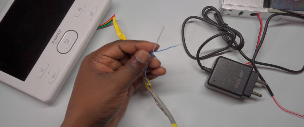
Step 3: Preparing the CAT6 Cable at the Indoor Screen
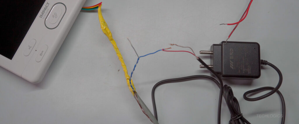
- Locate the CAT6 Cable: At the indoor screen end, carefully peel back or unwrap the insulation tape around the CAT6 cable to expose the internal wires. Take care to avoid damaging the wires.
- Identify the Blue Pair: Among the wire pairs, locate the blue pair (blue wire and white-blue wire), which are designated for the lock connection. Keep the brown pair intact for future use.
- Strip the Wires: Using a wire stripper, carefully remove about half an inch of insulation from each wire in the blue pair. Ensure enough copper is exposed for a firm connection without damaging the wire strands.
- Prepare the Power Supply Wires: Strip the output wires from your DC power supply in the same manner.
Proper wire preparation is critical for a secure electrical connection that won’t loosen or cause faults.
Step 4: Making the Power Connections
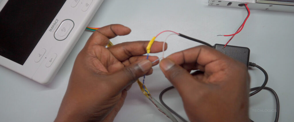
- Connect the Power Supply:
- Attach the positive terminal of the DC power supply to the blue wire.
- Connect the negative terminal to the white-blue wire.
- Verify Polarity: Refer to your wiring diagram to confirm correct polarity, as this is crucial for the lock’s operation.
- Secure the Connections: Ensure both connections are tight and free of loose strands to prevent short circuits or unreliable operation.
- Insulate the Connections: Wrap the joined wires thoroughly with electrical tape or appropriate insulating material to protect against moisture, accidental disconnection, or short circuits. Proper insulation ensures long-term reliability and safety.

Step 5: Wiring at the Door Station
At the door station, you’ll use a 3-wire cable designed for the Electromagnetic Lock, which includes:
- Common (COM): Acts as the return path.
- Normally Close (NC): The default connected state when the lock is not activated.
- Normally Open (NO): Not used in this setup.
Since the EM Lock operates in a Normally Closed (NC) configuration, focus on the COM and NC wires.
- Prepare the 3-Wire Cable: Strip the COM and NC wires carefully for secure connections.
- Connect the CAT6 Blue Pair:
- Assign the blue wire as the positive power line and connect it to the positive terminal of the EM Lock.
- Connect the white-blue wire (negative) to the door station’s COM wire.
- Connect the NC Wire: Attach the lock’s negative wire to the door station’s NC wire to maintain the lock in a closed state when not energized, enhancing security.
- Insulate All Connections: Use electrical tape or insulating material to secure all joints, preventing accidental shorts or electrical issues.


Step 6: Powering Up the System
- Connect and power on both the DC power adapter for the VDP and the power adapter for the lock.
- Check the lock’s LED indicator. A lit LED confirms that the lock is powered correctly and the connections are functioning as intended.

Step 7: Testing the Lock Function
- Initiate a Call: Make a call from the door station. When the indoor screen rings, press the Answer button to connect.
- View the Camera Feed: Once connected, the indoor screen will display the door station’s camera feed.
- Unlock the Door: While in communication mode, press the Key button to unlock the EM Lock. If the lock disengages, the electromagnet has demagnetized, allowing the door to open.
Note: The default unlock duration is approximately 1 second, which may be too short. For practical access, adjust the unlock time to at least 5 seconds (see below).

Step 8: Adjusting the Door Unlock Time
To ensure sufficient time for door access:
- Go to the Main Menu on the indoor screen.
- Navigate to the Mode settings.
- Locate Door 1 Unlock Time and set it to 5 seconds.
- Save the changes to apply the new unlock duration.
This adjustment ensures smooth and reliable door access.


Conclusion
Your Honeywell Impact Analog VDP with Electromagnetic Lock integration is now complete, including a customized door unlock duration. This setup provides a secure and efficient access control solution with proper wiring and insulation for long-term reliability.
For more in-depth guides on the Honeywell Impact Analog VDP system, explore our other tutorials. If you have questions or need further clarification, feel free to reach out. Stay tuned for more DIY electronics tips and tutorials!