In this comprehensive guide, we will walk you through the process of setting up the ELECROW ESP32 7.0 Inch HMI Display using the Arduino IDE. Whether you are a beginner or an experienced user, this tutorial will provide the necessary information and steps for integrating this impressive display into your projects.
Step 1: Install the Arduino IDE
Before we can get started, you need the Arduino Integrated Development Environment (IDE) installed on your computer. If you don’t have it installed, you can download it from the Arduino website. Follow the installation instructions appropriate for your operating system.
Once installed, locate the Arduino IDE on your computer—this can be on your desktop or within your applications folder. Double-click the icon to open it.
Step 2: Configure the Arduino IDE
Once the Arduino IDE is open, you will need to configure it for your ESP32 board. Start by clicking on File in the top menu bar, then select Preferences from the dropdown menu. This action will open a new window.
Step 2.1: Add Additional Board URLs
In the Preferences window, locate the Additional Board URLs field. This area allows you to add extra board types that the Arduino IDE can recognize. If you see any existing URLs, add a comma at the end of one and enter this URL:
https://dl.espressif.com/dl/package_esp32_index.json
This URL enables the IDE to access the board definitions necessary for the ESP32 platform. After entering the URL, click OK to save your changes and close the window.
stable release link : https://docs.espressif.com/projects/arduino-esp32/en/latest/installing.html
Step 3: Install the ESP32 Board Package
To work with the ESP32, you need to install its board package through the Board Manager.
Step 3.1: Open the Board Manager
In the Arduino IDE, go to the Tools menu, hover over Board, and select Board Manager. This action opens the Board Manager window.
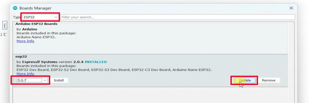
Step 3.2: Search for ESP32
In the Board Manager window, use the search bar at the top right corner and type ESP32. Look for the entry labeled esp32 by Espressif Systems. Click on it, and if an update is available, you will see an Update button. Click this button to install or update the package.
Step 3.3: Close the Board Manager
Once the installation is complete, close the Board Manager window.
Step 4: Download the Demo Code
To begin programming your ELECROW ESP32 Display, download the sample demo code needed for your project.
Step 4.1: Find the Demo Code on GitHub
Open your web browser and search for “Crow Panel ESP32 Display Course File.” This search will direct you to the GitHub repository containing the demo files for the ESP32 display.
Download Link : https://github.com/Elecrow-RD/CrowPanel-ESP32-Display-Course-File
Step 4.2: Download the ZIP File
Once on the GitHub page, find the green Code button. Click it and select Download ZIP.
Step 4.3: Extract the ZIP File
After the download is complete, locate the ZIP file in your downloads folder. Right-click on the file and select Extract All to unzip its contents. You will find various folders containing sample programming code categorized by display size and version.
Step 5: Open the Lesson 1 Code
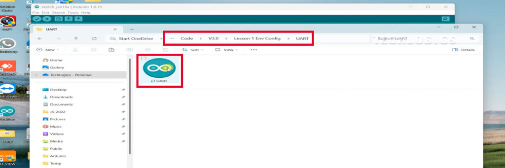
Now that you have extracted the files, navigate to the ‘code’ subfolder within the extracted folder.
Step 5.1: Navigate to the Lesson 1 Folder
Inside the ‘code’ subfolder, find the folder corresponding to the latest version, then open the folder labeled Lesson 1. This lesson will provide you with the initial code to test the display’s functionality.
Step 6: Configure Board Settings in Arduino IDE
Before uploading the code, you need to ensure all your board settings are correctly configured.
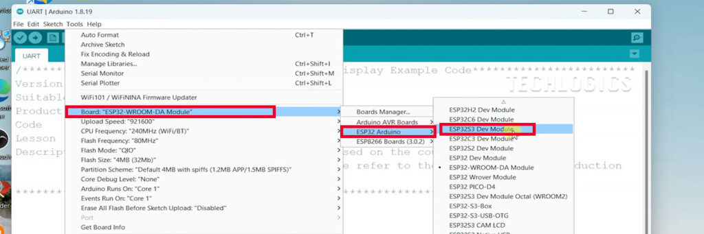
Step 6.1: Select the Correct Board
In the Arduino IDE, go to the Tools menu. In the Board section, select ESP32S3 Dev Module. This ensures that the IDE is aligned with your hardware specifications.
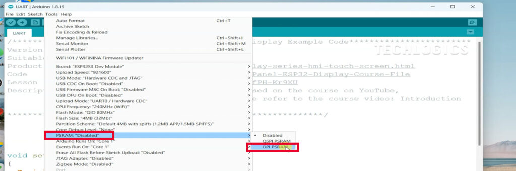
Step 6.2: Configure PSRAM Setting
Next, locate the PSRAM option in the Tools menu and set it to OPI PSRAM. This step is crucial for programs that require extra memory beyond the chip’s native capacity.
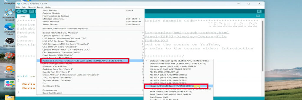
Step 6.3: Select Partition Scheme
Locate the Partition Scheme option in the Tools menu and select Huge App (3MB). This option allows your code to utilize more space, which is beneficial for applications with larger requirements.
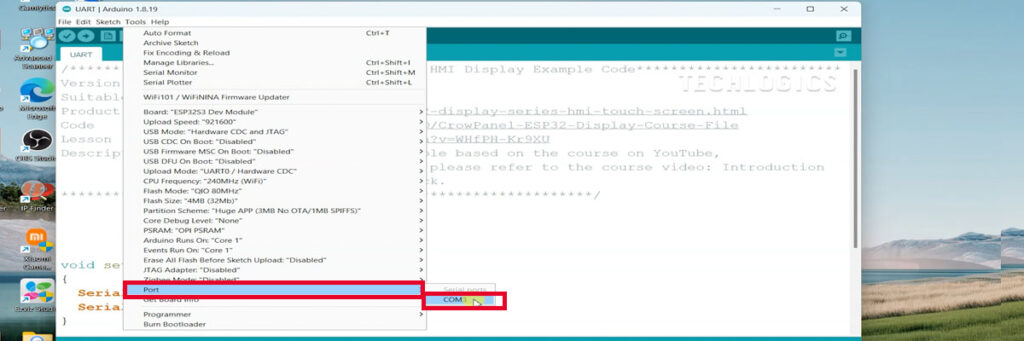
Step 6.4: Choose the Right USB Port
Lastly, ensure that the correct USB port corresponding to your ESP32 board is selected. To do this, go back to the Tools menu and look for the Port option. Click on it to reveal a dropdown list of available COM ports. If you have multiple devices connected, identify and select the port that corresponds to your ESP32 display. This step is critical for establishing a successful connection during code upload. Make sure that the USB data cable is securely connected between the ESP32 display panel and your computer.
Step 7: Compiling and Uploading Your Code
With the board settings properly configured, you are now ready to compile and upload the demo code to the ESP32 display panel.
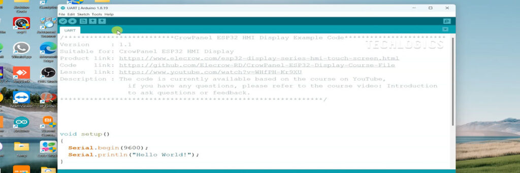
Step 7.1: Open the Demo Code
In the Arduino IDE, click on File -> Open, and navigate to the ‘Lesson 1’ folder you opened earlier. Select the appropriate code file, usually named something like Lesson1.ino, and open it in the Arduino IDE.
Step 7.2: Compile the Code
Before uploading, it’s a good practice to compile the code to check for any syntax errors. To compile, click the checkmark icon (✓) in the top left corner of the IDE. The IDE will process the code and indicate if there are any errors. If errors are detected, address them before proceeding.
Step 7.3: Upload the Code
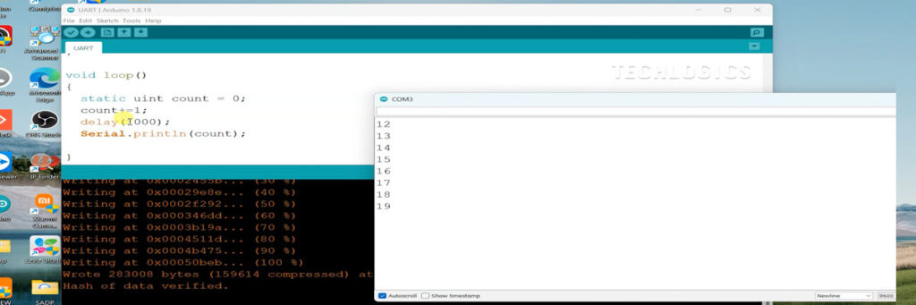
Once the code is compiled without errors, click the upload button (the right arrow icon) to begin uploading the sketch to the ESP32 display panel. You will see the messages in the bottom of the IDE notifying you of the upload progress. Wait for the upload to complete, which usually takes just a few moments.
Step 8: Viewing Output on the Serial Monitor
After the upload is successful, it’s essential to verify that your code is functioning as expected. For this, you will use the Serial Monitor.
Step 8.1: Open the Serial Monitor
In the Arduino IDE, click on Tools, then select Serial Monitor from the dropdown menu. Alternatively, you can click the magnifying glass icon located in the upper right corner of the IDE.
Step 8.2: Set Baud Rate
Once the Serial Monitor opens, set the baud rate to 9600. This value should match the baud rate defined in your code (commonly the default setting). This setting ensures that you can correctly receive and view the output from the ESP32.
Step 8.3: Observe the Output
Run your program, and you should see the counter incrementing in the Serial Monitor. This output confirms that the program is functioning properly, indicating that your ESP32 and Arduino IDE are communicating effectively.
To further your skills with the ELECROW ESP32 7.0 Inch HMI Display, follow these detailed steps to load the second lesson from the downloaded code.
Step 1: Accessing Lesson 2 Code
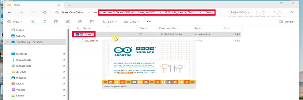
Begin by navigating to the ‘code’ subfolder within the folder you previously extracted. Inside this folder, you’ll find a subfolder labeled Lesson 2. Open this folder to discover a subfolder specifically named 7 Inch Display. This subfolder contains the simple GUI code designed for the 7-inch display, including example sketches and resources that illustrate how to create basic graphical user interfaces on the ESP32 display.
Step 2: Reviewing Lesson 2 Code
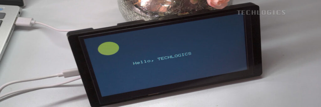
Take your time to carefully review the code provided in this lesson. Understanding how the code operates will serve as a foundation for creating your own GUI elements on the display panel, such as text fields and images. By experimenting with the sample code, you can enhance your programming skills with the ESP32 and its display functionalities.
Step 3: Modifying Configuration Settings
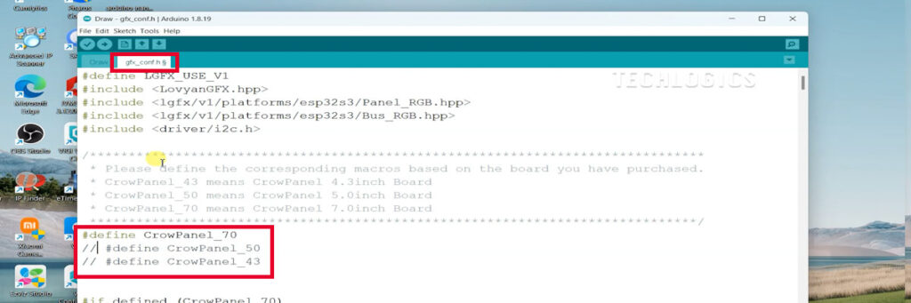
In the main code for the 7-inch display, you will encounter a configuration file named gfx_conf.h. This file is crucial for setting the display parameters specific to your board size.
3.1: Edit the gfx_conf.h File
Open the gfx_conf.h file in your code editor. Look for the section that defines the display sizes. You will typically see lines that indicate the options available for different display sizes.
To select the 7-inch display size, ensure that the line:
#define CrowPanel_70
is uncommented by removing the // at the beginning of that line. This change allows the code to recognize and utilize the settings specific to the 7-inch display. Conversely, if there is a line defining the 5-inch display, such as:
//#define CrowPanel_50
be sure it remains commented out by keeping the // intact. After making these changes, save the adjustments in the gfx_conf.h file.
Step 4: Installing Necessary Libraries
To utilize the features of the ELECROW ESP32 HMI Display in your project, it’s essential to install the ‘LovyanGFX’ library. This library provides the graphical functions needed for display operations.
4.1: Open the Arduino IDE and Access Library Manager
Start by opening the Arduino IDE and navigating to the Library Manager. You can access this by clicking on Sketch in the top menu, then selecting Include Library followed by Manage Libraries.
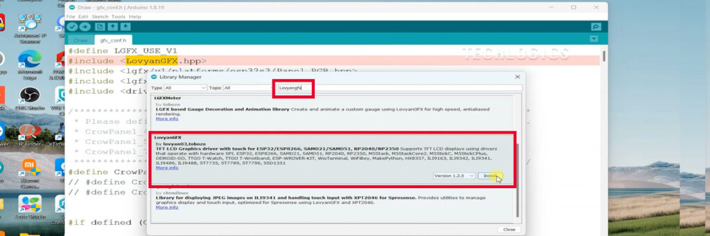
4.2: Search for and Install LovyanGFX
In the Library Manager window, type “LovyanGFX” into the search bar located at the top right corner. Select the ‘LovyanGFX’ library from the results and click the Install button. Wait for the installation process to finish, ensuring the library is successfully added to your Arduino IDE environment.
Step 5: Installing PCA9557 Library
In addition to the ‘LovyanGFX’ library, you will also need the ‘PCA9557’ library to ensure your code works properly with the ELECROW ESP32 7.0 Inch HMI Display.
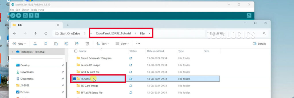
5.1: Locate the PCA9557 Folder
This library is included in the folder you downloaded earlier. Navigate to the ‘files’ subfolder within your downloaded code, and find the folder named ‘PCA9557’.
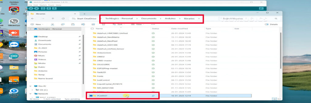
5.2: Copy the PCA9557 Folder
Copy the ‘PCA9557’ folder to your clipboard. Next, navigate to the Arduino libraries folder on your computer. This folder is typically found in your documents directory under Arduino/libraries. If you are unable to find it, you can check the Arduino IDE preferences for the specific path to the libraries folder.
5.3: Paste the PCA9557 Folder
After reaching the correct libraries folder, paste the ‘PCA9557’ folder into this directory. After placing the folder, restart the Arduino IDE to ensure that it recognizes the new library. Once the IDE restarts, you should be able to include the ‘PCA9557’ library in your sketches and access its functionality for your HMI display project.
Step 6: Finalizing Board and Configuration Settings
To finalize your ESP32 project setup, it is crucial to select the correct board and configurations in the Arduino IDE.
6.1: Select the Board Type
Start by navigating to the Tools menu. From the list of available boards, choose “ESP32S3 Dev Module.” This selection ensures that you are using the appropriate board type for your display.
Step 6.2: Configure the PSRAM Option
Next, locate the PSRAM option in the Tools menu. Set this option to “OPI PSRAM.” This adjustment is vital for applications that require additional memory beyond what is available on the main chip. By enabling OPI PSRAM, your ESP32 can run more complex programs and handle larger data set operations, particularly useful when working with graphics on the HMI display.
Step 6.3: Set the Partition Scheme
Following the PSRAM configuration, you will need to set the Partition Scheme. In the Tools menu, find this option and select “Huge App (3MB).” This particular partition scheme provides ample space for your applications, allowing them to function efficiently on the ESP32 without running into memory constraints. Choosing the right partition scheme is crucial for maximizing the performance of your projects, especially when dealing with demanding display operations.
Step 6.4: Choose the Right USB Port
Lastly, ensure that the correct USB port corresponding to your ESP32 board is selected. To do this, go back to the Tools menu and look for the Port option. Click on it to reveal a dropdown list of available COM ports. If you have multiple devices connected to your computer, make sure to identify and select the port that corresponds to your ESP32 display. This step is critical for establishing a successful connection during code uploads. Make sure that the USB data cable is securely connected between the ESP32 display panel and your computer.
Step 7: Compiling and Uploading Your Code
With the board settings properly configured, you are now ready to compile and upload the demo code to the ESP32 display panel.
Step 7.1: Open the Demo Code
In the Arduino IDE, click on File -> Open, and navigate to the ‘Lesson 1’ folder you opened earlier. Select the appropriate code file, usually named something like Lesson1.ino, and open it in the Arduino IDE.
Step 7.2: Compile the Code
Before uploading, it’s a good practice to compile the code to check for any syntax errors. To do this, click the checkmark icon (✓) in the top left corner of the IDE. The IDE will process the code and indicate if there are any errors. If errors are detected, you’ll need to address them before proceeding.
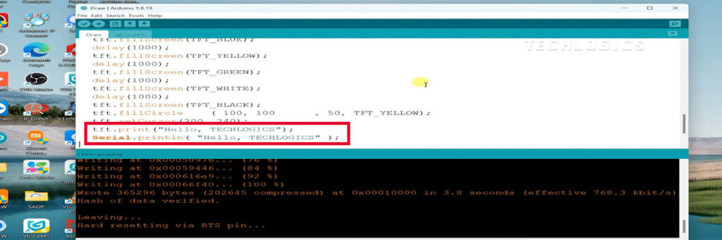
Step 7.3: Upload the Code
Once the code compiles without any errors, click the upload button (the right arrow icon) to begin uploading the sketch to the ESP32 display panel. You will see messages in the bottom of the IDE notifying you of the upload progress. Wait for the upload to complete, which usually takes just a few moments.
Step 8: Viewing Output on the Serial Monitor
After the upload is successful, it’s essential to verify that your code is functioning as expected. For this, you will use the Serial Monitor.
Step 8.1: Open the Serial Monitor
In the Arduino IDE, click on Tools, then select Serial Monitor from the dropdown menu. Alternatively, you can click the magnifying glass icon located in the upper right corner of the IDE.
Step 8.2: Set Baud Rate
Once the Serial Monitor opens, set the baud rate to 9600. This value should match the baud rate defined in your code (commonly the default setting). Setting the correct baud rate ensures that you can accurately receive and view the output from the ESP32.
Step 8.3: Observe the Output
Run your program, and you should see the counter incrementing in the Serial Monitor. This output confirms that the program is functioning properly, indicating that your ESP32 and Arduino IDE are communicating effectively.
Step 9: Advancing to Lesson 2
With the counter increment successfully displayed, you’re ready to move on to Lesson 2 of your tutorial. This lesson will introduce you to displaying simple text and graphics on the ESP32 HMI display.
Step 9.1: Load Lesson 2 Code
To continue your learning, navigate back to the ‘code’ subfolder in your previously extracted files. Look for the subfolder labeled Lesson 2 and open it. Within this folder, you will find a subfolder named 7 Inch Display that contains the simple GUI code designed specifically for the 7-inch display.
Conclusion
This detailed step-by-step tutorial has walked you through the process of setting up the ELECROW ESP32 7.0 Inch HMI Display, configuring the Arduino IDE, and uploading demo code. With your setup confirmed and functional, you’re now ready to explore more advanced features and create interactive applications using your display. If you have any questions or need further assistance, feel free to refer to the additional resources linked in this tutorial or within your downloaded files. Happy coding!