In this tutorial, you will learn how to wire and program a dual 4-digit 7-segment display with an ESP32 Node MCU to display numbers. This project is perfect for beginners and DIY enthusiasts looking to add simple visual output to their electronics projects.
We’ll guide you step-by-step through the entire process, from setting up the hardware connections to coding in the Arduino IDE. By the end of this tutorial, you’ll understand how to wire an ESP32 to two 4-digit 7-segment displays (common anode, red). Let’s dive into the details!
Materials You’ll Need:
- ESP32 Node MCU
- 2 x 4-Digit 7-Segment Displays
- Header Pins
- PCB Board (9×15 cm)
Choosing the Right PCB Design
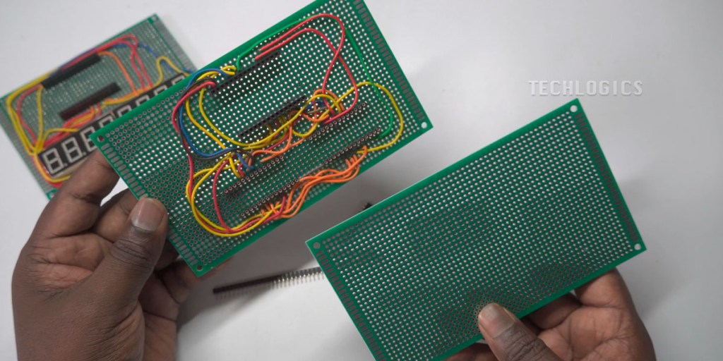
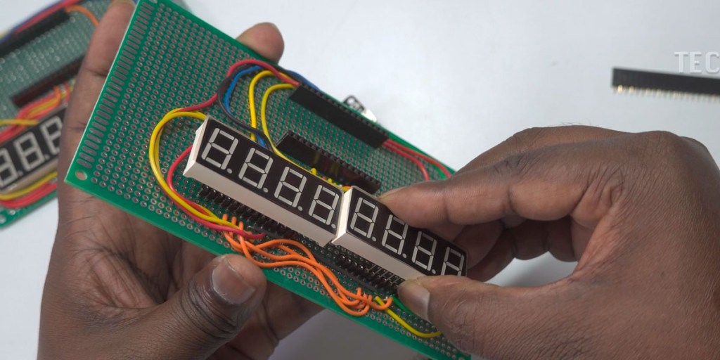
In this demonstration, we showcased two types of PCBs for wiring the 7-segment LED displays. The first type features the LED displays soldered directly onto the PCB board, offering a compact and fixed setup. The second type uses header pins, which make it much easier to replace the displays if needed. Additionally, using header pins allows the display to protrude slightly, making it suitable for mounting directly behind a front glass panel, which provides a cleaner, more professional look. The directly soldered PCB, on the other hand, is better suited for applications where display replacement or precise alignment isn’t a concern.
For optimal flexibility and ease of use, we recommend soldering both the ESP32 and the LED display onto the PCB using Female Header Single Row Straight Round Pins. This method enables you to remove and replace components without de-soldering, making future maintenance or upgrades much more convenient.
Assembling the PCB
To begin assembling the PCB, first place the ESP32 and the LED display onto the PCB through the female header pins, aligning them as shown in the video. Ensure that both components are seated securely and straight. Once the components are positioned, solder all the header pins to the PCB to establish a firm connection for both the ESP32 and the LED display. This setup not only provides stability but also allows for easy removal and replacement of components without damaging the PCB.
Wiring the Connections
Now that your components are secured, it’s time to wire the connections between the ESP32 and the 7-segment displays. We will start by wiring the segments of both displays.
Here’s how to wire the segments step by step:
Segment A: Connect Segment A of both displays in parallel (join their Segment A terminals together), then connect this combined terminal to ESP32 Pin 13.


Segment B: Connect Segment B of both displays in parallel, then connect this combined terminal to ESP32 Pin 14.


Segment C: Connect Segment C of both displays in parallel, then connect this combined terminal to ESP32 Pin 27.


Segment D: Connect Segment D of both displays in parallel, then connect this combined terminal to ESP32 Pin 26.


Segment E: Connect Segment E of both displays in parallel, then connect this combined terminal to ESP32 Pin 25.


Segment F: Connect Segment F of both displays in parallel, then connect this combined terminal to ESP32 Pin 33.


Segment G: Connect Segment G of both displays in parallel, then connect this combined terminal to ESP32 Pin 32.


Decimal Point (DP): Connect the DP terminal of both displays in parallel, then connect this combined terminal to ESP32 Pin 12.


Once these segment connections are made, proceed to wire the digit controls for both displays.
Wiring the Digit Controls
For Display 1 (first 4 digits):
Connect DIGIT1 of Display 1 to ESP32 Pin 4.

Connect DIGIT2 of Display 1 to ESP32 Pin 15.

Connect DIGIT3 of Display 1 to ESP32 Pin 18.

Connect DIGIT4 of Display 1 to ESP32 Pin 5.

For Display 2 (last 4 digits):
Connect DIGIT1 of Display 2 to ESP32 Pin 19.

Connect DIGIT2 of Display 2 to ESP32 Pin 21.

Connect DIGIT3 of Display 2 to ESP32 Pin 22.

Connect DIGIT4 of Display 2 to ESP32 Pin 23.

Uploading the Code to the ESP32
Once you’ve completed the wiring, connect your ESP32 board to your PC or laptop using a USB cable. This will power the ESP32.
#include <Arduino.h>

// Define segment pins (A-G and DP) for ESP32, shared between both displays
const int segmentPins[] = {13, 14, 27, 26, 25, 33, 32, 12}; // A-G, DP

// Define digit pins for Display 1 (Common Cathode)
const int digitPins1[] = {4, 15, 18, 5}; // DIG1-DIG4 for Display 1

// Define digit pins for Display 2 (Common Cathode)
const int digitPins2[] = {19, 21, 22, 23}; // DIG1-DIG4 for Display 2

// Segment encoding for numbers 0-9
const byte digits[10] = {
  0b00111111,  // 0
  0b00000110,  // 1
  0b01011011,  // 2
  0b01001111,  // 3
  0b01100110,  // 4
  0b01101101,  // 5
  0b01111101,  // 6
  0b00000111,  // 7
  0b01111111,  // 8
  0b01101111   // 9
};

// Combined 8-digit number to display
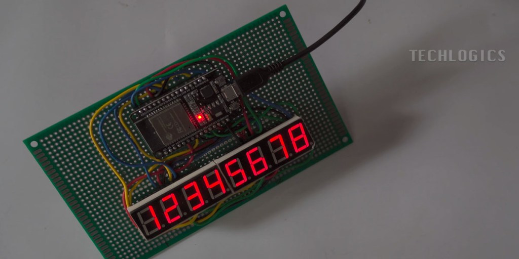
long number = 12345678; // Use decimal number, no leading zero

void setup() {
  // Set segment pins as outputs
  for (int i = 0; i < 8; i++) {
    pinMode(segmentPins[i], OUTPUT);
  }

  // Set digit pins for Display 1 as outputs
  for (int i = 0; i < 4; i++) {
    pinMode(digitPins1[i], OUTPUT);
    digitalWrite(digitPins1[i], HIGH); // Turn off all digits on Display 1 initially
  }

  // Set digit pins for Display 2 as outputs
  for (int i = 0; i < 4; i++) {
    pinMode(digitPins2[i], OUTPUT);
    digitalWrite(digitPins2[i], HIGH); // Turn off all digits on Display 2 initially
  }
}

void loop() {
  displayNumber(number); // Display the number on both displays
}

// Function to display an 8-digit number on the combined 8-digit display
void displayNumber(long number) {
  // Extract each digit from the 8-digit number
  int digitsToShow[] = {
    (number / 10000000) % 10,
    (number / 1000000) % 10,
    (number / 100000) % 10,
    (number / 10000) % 10,
    (number / 1000) % 10,
    (number / 100) % 10,
    (number / 10) % 10,
    number % 10
  };

  // Display each digit on the corresponding display
  for (int i = 0; i < 8; i++) {
    int digitPin = (i < 4) ? digitPins1[i] : digitPins2[i - 4]; // Decide which digit pin to use
    showDigit(digitsToShow[i], digitPin); // Show current digit
    delay(2); // Adjust this delay to control flicker (lower means less flicker)
  }
}

// Function to show a single digit at a specific position
void showDigit(int digit, int digitPin) {
  // Set segments for the specific digit
  byte segmentValue = digits[digit];

  // Write segment states
  for (int i = 0; i < 8; i++) {
    digitalWrite(segmentPins[i], (segmentValue >> i) & 1); // Write segment state
  }

  // Activate the specific digit (active LOW)
  digitalWrite(digitPin, LOW); // Turn on the digit
  delayMicroseconds(500); // Hold the digit on for a short time
  digitalWrite(digitPin, HIGH); // Turn off the digit
}
Next, open the Arduino IDE on your computer. In the IDE, load the sample code provided in the video description. This code is specifically designed to test the display and show numbers on the LED display.
Ensure that you’ve selected the correct ESP32 board and port in the Arduino IDE. Follow these steps:
- Go to Tools > Board, and select the correct ESP32 board model.
- Go to Tools > Port, and select the port to which your ESP32 is connected.
Once you’ve made these selections, click the Checkmark (✓) button to compile the code. The IDE will verify for any errors in the code.
If the code compiles successfully without errors, click the Upload button (the right arrow) to upload the code to the ESP32. After the upload completes, a confirmation message will appear, indicating that the code has been uploaded successfully.

Testing the Display
Your ESP32 will now start executing the code, and the LED display should show the desired output based on the uploaded code. You can experiment with different numbers or display patterns by modifying the code.
Conclusion
This project provides a simple yet effective way to add visual output to your electronics projects using an ESP32 and a dual 4-digit 7-segment display. It’s a great way for beginners to learn about wiring, coding, and using the Arduino IDE with the ESP32.
For further clarification, we’ve included in-depth explanations of these features in other segments of this video series. Additionally, you’ll find more code examples related to LED display projects, helping you expand your skills and explore more creative applications.
If this tutorial was helpful, please consider supporting us by liking, sharing, or subscribing to our channel. Your support allows us to continue creating valuable content and resources for our audience. Thank you for your support!


