Welcome to TECH LOGICS! Today, we’re diving into an exciting Arduino project that captures IR remote signals and displays their hexadecimal codes on an 8-digit 7-segment display using the MAX7219 module and an ESP32. Whether you’re new to Arduino or a seasoned maker, this project is fun, practical, and a great way to learn about IR communication and LED displays. Let’s get started!
What You’ll Need
Before we jump in, here’s what you’ll need to build this project:
- ESP32 or Arduino-compatible microcontroller: This is the brain of our setup.
- MAX7219 8-digit 7-segment display module: This displays the hex codes in a clear, vibrant format.
- IR receiver (e.g., TSOP1838): This captures infrared signals from your remote.
- Jumper wires and a breadboard: These help you connect everything neatly. Alternatively, you can solder components onto a PCB, as shown in our wiring diagram.
- Computer with Arduino IDE installed: You’ll also need two libraries: LedControl for the display and IRremotefor the IR receiver.
Check out the wiring diagram and code at the end of this post for easy access to all resources!
BUY ONLINE
Hardware Setup
Let’s wire up the components to get your project ready:
- Connect the MAX7219:
- VCC to 5V or 3.3V (check your module’s specs).
- GND to GND on your ESP32.
- DIN to GPIO 23.
- CLK to GPIO 18.
- CS to GPIO 5.
- Connect the IR receiver:
- VCC to 3.3V or 5V (match your receiver’s requirements).
- GND to GND.
- Signal pin to GPIO 15.
- Use a breadboard for prototyping or solder onto a PCB for a permanent setup, as shown in our wiring diagram.

Double-check your connections to avoid issues later. If you’re using a different microcontroller, you may need to adjust the pin assignments in the code.
Installing the Libraries
To make this project work, we need two libraries: LedControl for the MAX7219 and IRremote for decoding IR signals. Here’s how to install them:
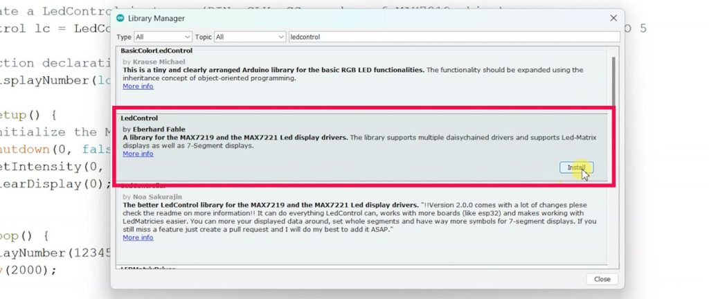
- Open the Arduino IDE and go to Sketch > Include Library > Manage Libraries.
- Search for LedControl by Eberhard Fahle, select the latest stable version, and click Install. This library simplifies controlling the MAX7219 display, letting you set digits, characters, and brightness.
- For IRremote, you have two options:
- Via Library Manager: Go to Sketch > Include Library > Manage Libraries, search for “IRremote” by Armin Joachimsmeyer, and install the latest version.
- Via GitHub: Search for “IRremote library” on Google to find the official GitHub page. Download the latest release ZIP file by Armin Joachimsmeyer, extract it, and copy the inner IRremote folder to your Arduino libraries directory (typically Documents/Arduino/libraries). Avoid nesting subfolders like “IRremote-main” to prevent errors.

If you see a “fatal error: avr/pgmspace.h” during compilation, open the LedControl folder (Documents/Arduino/libraries/LedControl), find #include <avr/pgmspace.h> in LedControl.cpp or LedControl.h, comment it out with //, and save. If the IRremote library causes issues, ensure the extracted folder is directly in Documents/Arduino/libraries without extra subfolders.


Configuring the Arduino IDE
To ensure smooth communication between your ESP32 and the MAX7219:
- Open the Arduino IDE and go to Tools > Board. Select your ESP32 board, such as “ESP32 Dev Module.”
- Under Tools > Port, choose the correct port (e.g., COM3 or /dev/ttyUSB0). If unsure, check your computer’s device manager or unplug and replug the ESP32 to identify it.
- Verify your board and port settings to avoid upload errors.
Uploading the Code
Grab the complete Arduino sketch from the link provided in the resources section below. This code is fully tested to match our demo, displaying IR hex codes on both the Serial Monitor and MAX7219 display. You can customize it—adjust brightness, change pins, or add features like storing multiple IR codes—to suit your needs.
#include <LedControl.h>
#include <IRremote.hpp>

// Initialize MAX7219 display
LedControl lc = LedControl(23, 18, 5, 1);
#define IR_RECEIVE_PIN 15

uint64_t lastDisplayedCode = 0;

void setup() {
  Serial.begin(9600);
  Serial.println("Starting IR receiver...");

  // Setup IR receiver
  IrReceiver.begin(IR_RECEIVE_PIN, false);

  // Setup MAX7219
  lc.shutdown(0, false);
  lc.setIntensity(0, 8);
  lc.clearDisplay(0);
}

void loop() {
  if (IrReceiver.decode()) {
    uint64_t rawData = IrReceiver.decodedIRData.decodedRawData;
    if (rawData != 0 && rawData != lastDisplayedCode) {
      // Print serial only if new code
      Serial.print("HEX code: ");
      Serial.println(rawData, HEX);

      // Show only last 8 hex digits, uppercase, no leading zeros
      displayHex(rawData);

      lastDisplayedCode = rawData; // update last code
    }
    IrReceiver.resume();
  }
  delay(10);
}

// Function to display only significant hex digits in uppercase
void displayHex(uint64_t data) {
  uint32_t last8 = (uint32_t)(data & 0xFFFFFFFF);

  // If data is zero, blank display
  if (last8 == 0) {
    for (int i=0; i<8; i++) {
      lc.setDigit(0, i, 10, false); // blank
    }
    return;
  }

  // Find the most significant non-zero nibble
  int startDigit = 0;
  for (int i=7; i>=0; i--) {
    int digit = (last8 >> (4*i)) & 0xF;
    if (digit != 0 || i==0) {
      startDigit = i;
      break;
    }
  }

  // Clear display
  for (int i=0; i<8; i++) {
    lc.setDigit(0, i, 10, false); // blank
  }

  // Show significant hex digits in uppercase
  int displayPos = 7;
  for (int i=startDigit; i>=0; i--) {
    int digit = (last8 >> (4*i)) & 0xF;
    if (digit < 10) {
      // digits 0-9
      lc.setDigit(0, displayPos--, digit, false);
    } else {
      // A-F uppercase letters
      char c = 'A' + (digit - 10);
      lc.setChar(0, displayPos--, c, false);
    }
  }
}Once your libraries are installed, open the sketch in the Arduino IDE. Click the Upload button (right-arrow icon) with your ESP32 connected via a USB cable that supports data transfer. If you encounter upload issues, double-check the port in Tools > Port and ensure your cable isn’t power-only. After a successful upload, your ESP32 will run the code, and you’re ready to test!
Testing the IR Remote Display
With the code uploaded, let’s test the setup:
- Open the Arduino IDE’s Serial Monitor (Tools > Serial Monitor) and set the baud rate to 9600 to match the code.
- Point your IR remote (e.g., from a TV or AC) at the TSOP sensor and press a button.
- Watch the hex code appear instantly on both the Serial Monitor and the MAX7219 display!
The MAX7219 can show up to eight characters of the hex value, trimming longer codes to the last eight digits for a clean display. The Serial Monitor, however, will show the full code if it exceeds eight characters. If the display or Serial Monitor doesn’t work, ensure the TSOP sensor is unobstructed, the baud rate is correct, and all connections are secure.


Troubleshooting Tips
Here are quick fixes for common issues:
- No display output: Check wiring, increase brightness in the code (lc.setIntensity(0, 8)), or verify the MAX7219’s power supply.
- Serial Monitor gibberish: Confirm the baud rate is 9600 in both the code and Serial Monitor.
- Upload fails: Ensure the correct board and port are selected, and use a data-capable USB cable.
- Library errors: See the library installation section for avr/pgmspace.h and IRremote subfolder fixes.
What’s Next?
We’re just getting started! In our upcoming posts, we’ll explore more ways to display hex codes, including a project using an LCD display to show longer values for greater flexibility. These tutorials will help you enhance your smart home setup and unlock the full potential of your Arduino projects.
Resources
- Wiring Diagram and Code: [Insert link to GitHub/Pastebin or hosting platform]
- LedControl Library: Available via Arduino IDE Library Manager
- IRremote Library: Available via Arduino IDE Library Manager or GitHub
Join the TECH LOGICS Community
If you enjoyed this project, please support us by leaving a comment, sharing this post, or following TECH LOGICS for more Arduino tutorials. Your support helps us create valuable content for makers like you. Got questions or ideas for future projects? Drop them in the comments below—we’d love to hear from you! Stay tuned for our next post on using an LCD display for even more hex code fun!